Quick Guide
Here are some core concepts to get you started creating projects. This guide will cover the basics of the app and how to use it, please refer to the reference sections for more details.
We have also prepared a video guide that covers the same topics as this written guide. You can watch it below or on our YouTube channel.
Library
Everyone has access to the default library which includes a variety of gear. We have hundreds of library items and we will continue to add more gear to the library over time. If there is something you would like added, please let us know!
In addition, every Pro user has their own user library where you can copy items from the default library, customize them, and save them for yourself. Teams also have their own shared team library, allowing all team members to access and use custom library items. Library items are agnostic to projects, meaning you can use them across all your projects (Pro feature).
Each piece of gear in the library belongs to a brand, and each brand belongs to a manufacturer. In addition, each piece of gear has a type (lighting console, speaker, media server, etc.).
While all categories have access to the full range of ports, some categories have additional features such as switches (IP address), or a lighting fixture (DMX mode). These are features that will continue to be expanded upon.
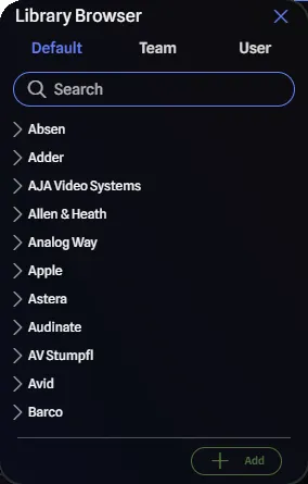
From the Library Browser Pane, you can either click the Add button or drag-and-drop gear into your project to start using it.
Gear
When you insert gear into the drawing, you can customize it to fit your needs. Different categories have different options, but all gear has Detail Mode and Reverse Port Placement.
By default, GearConnect will auto-select Detail Mode if the gear item has more than four ports on it, including any ports from default expansion cards. The difference between detail and normal modes is that in Detail Mode, all the ports are on the left and right and the ports have labels. In Standard Mode, the ports are on the top and bottom without labels.
- Detail Mode: Great for switches or consoles that have a lot of different connectors.
- Standard Mode: Great for simple devices like lighting fixtures or speakers that only have a couple of ports.
When in Detail Mode, Default mode will spread the ports evenly left and right, based on port groupings (for example, all DMX out on one side, all DMX in on the other). But you can choose to place all the ports on either the Left or Right side.
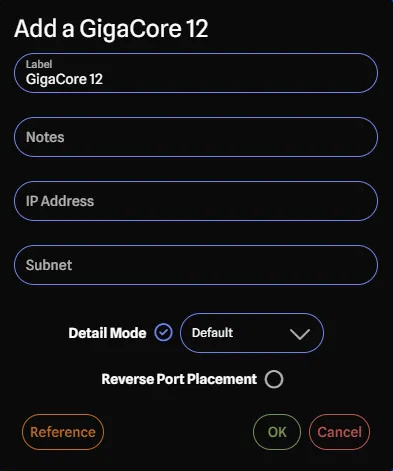
Reverse Port Placement will simply flip the ports that would have been on the left to the right and vice versa. Available for Detail Mode using the Default port placement or Standard Mode.
Expansion Cards
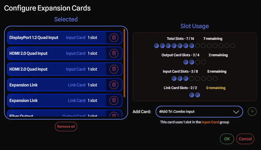
If the gear item has expansion cards, you can select them on this dialog from the Configure Expansion Cards button. Each gear knows how many expansion cards it can support, and will let you add additional cards until it reaches the maximum.
Some cards even have additional properties such as:
- Groups: If applicable, expansion cards are grouped together. For example, into Input or Output groups.
- Group Limit: Some groups may have a maximum number of cards that can be added to them.
- Slot Size: Most cards take up 1 slot, but some may require more, taking up multiple slots in the gear item.
The dialog provides the following features for managing expansion cards:
- Display of Available Cards: Shows all expansion cards that can be added to the gear item; if a card is disabled, it means it cannot be added due to slot limitations or group restrictions.
- Slot Size Validation: Once you have reached the maximum number of slots (either total or per group), the dialog will prevent you from adding more cards until you remove some existing ones.
- Real Time Feedback: You can track how many slots are used and how many are available in real-time as you add or remove cards with the indicators on the right side of the dialog.
Adding and Removing Cards
You can add expansion cards by selecting from the Add Card dropdown and clicking the Plus icon. The dropdown only allows you to add cards that can fit within the remaining slot capacity and group limitations.
To remove cards, click the Trash icon next to individual cards or use the Remove all button to clear all selected cards at once.
Group Expansion Ports
When there are expansion cards on the gear item and you have enabled Detail Mode, you can choose to group the ports by their expansion card via the Group Expansion Ports button. When adding new gear that has default expansion cards, Group Expansion Ports will be enabled by default. Learn more about this feature in Group Expansion Ports.
Making Connections
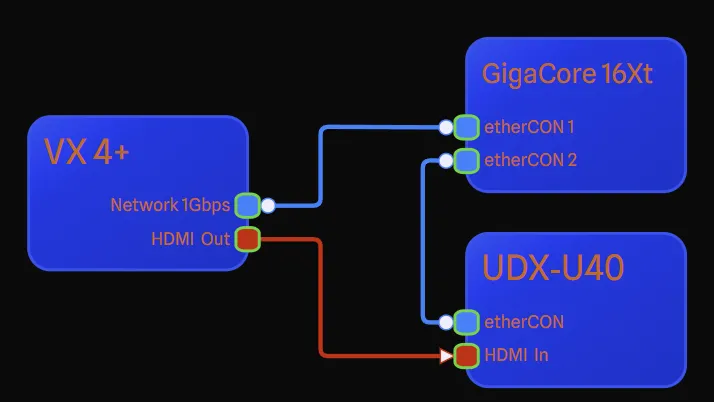
To create a connection, simply click on a port and drag to another port. The app will then validate if the connection is a valid connection and reject it if not (with an explanation as to why). The end of the line will either be a circle for bidirectional connections or an arrow for unidirectional connections.
Ports are colour-coded based on their type. By default, the connection will be the same colour. You can change the colour of the connection to either be the layer colour or a custom colour by right-clicking or changing it on the Report Page. Colors of ports usually mean other ports of the same colour can be connected together.
Each port has several different data points, some of which help determine compatible connections:
- Connected Gear: The gear item that is connected to this port via a connection.
- Label: The name of the port.
- Category: The category of the port (Network, Audio, Lighting, etc.). These are used mostly for labeling purposes and don’t affect connection validation.
- Connector: The physical connector on the device (RJ45, XLR 5-Pin, OpticalCon Duo SMF, etc.). Connectors are organized by category for easy selection. These determine the colour that appears in the drawing for the port. This is used for validation.
- Direction: This refers to the physical direction of the port, determining how the cable is plugged in, based on pin orientation. For most ports, the direction is bidirectional since most ports, like RJ45 or BNC, have the same male or female port on the device. However, for ports like XLR, which can have different male and female pin directions for inputs and outputs, we use Direction to specify. (Input, Output, Bidirectional). This is used for validation.
- Signal Type: This is the type of signal that will be sent or received from this port (SDI, sACN, MIDI, etc.). Signal types are organized by category for easy selection. This is used for validation.
- Signal Flow: This is the direction of the signal flow. (Input, Output, Bidirectional). This is the not the physical direction of the pins on the port, just the flow of data. For example, an SDI BNC port will physically both be the same port direction on the two connecting devices, but the signal flow usually only goes one way. This is used for validation.
- Speed: For some ports, a speed is also provided. For network ports, this may be 1Gbps, 10Gbps, etc. For SDI ports, this may be HD-SDI, 3G-SDI, etc. This is not used for validation.
- Sort Order: The sort within the port’s grouping. For example, all DMX Outs might be numbered from 1-8 while DMX Ins could be numbered from 1-4. Renumbering DMX In 1 to DMX In 5 would change DMX Ins to be 2-5, while maintaining 1-8 for DMX Outs.
- Expansion Card: (Only available if the port belongs to an expansion card) The library item this
port belongs to. This will be an expansion card that was selected when the gear was added to the project.
- This will also include a number, for example you may see “DisplayPort 1.2 Quad Output (2)” which would indicate that this is the second expansion card of this type that was added to gear.
All categories except switches support IP Addresses if the connector is included in the connector type list here. If so, the port will have the following additional fields:
- DHCP: Whether the port uses DHCP for automatic IP address assignment.
- IP Address: The IP address of the port. Displays “DHCP” in Reports when DHCP is enabled.
- Subnet: The subnet of the port. Displays “DHCP” in Reports when DHCP is enabled.
These properties’ initial data come from the related properties from the library item the gear was generated from (where applicable). For this initial data these options are customizable in the Library Editor (Pro feature). Once inserted into the drawing you can also activate Full Edit Mode (Pro feature) to fully edit all port options as well.
Selecting Items
Click on any item in the drawing to select it. For multiple items, hold Shift and click, or
click and drag on an empty area to create a selection box. When items are selected, a
Selection Toolbar appears with quick actions like editing labels, duplicating, aligning,
and more.
For detailed information on selection modes, filtering, and all available actions, see the Selection Toolbar page.
My Gear
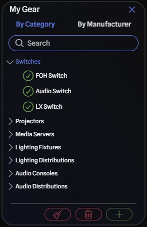
As you add gear to your project, it will show up in the My Gear pane. This is a list of all the gear you have added to the project and is a great way to see all the gear in one place.
The checkmarks on the gear indicate if the gear is in the drawing or not. When you select a piece of gear in the drawing, it will be selected in the My Gear pane and vice versa.
By default when you remove gear from the drawing it will simply be marked as not used in the drawing. You can also remove gear from the project entirely by selecting the gear you would like to delete and clicking the Delete button.
Deleting gear will remove all ports and connections, including any ports you have customized. This is a good way to reset the gear back to its default state based on its library item. Properties that will persist are gear-specific settings you configured, like label, IP address, and Detail Mode.
Editing Gear
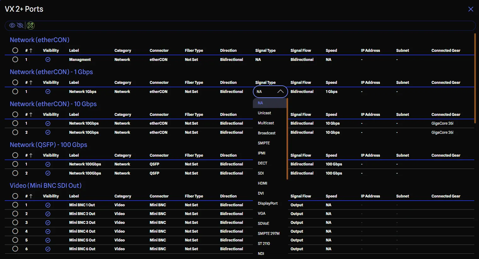
You can access all port options for a given piece of gear by selecting it, and clicking on View all
details in the Device Config pane, or by using the keyboard shortcut Ctrl+D (or Cmd+D on
Mac). From here you can relabel ports, change their sort order, and even hide ports you aren’t using.
If a port has configurable options (like different signal types) then they will appear here as well for you to select. Otherwise, you can enable Full Edit Mode (Pro feature) from the toolbar which allows you to edit all the port options, even if they are not normally visible. From here, you can change any of the port options listed above, so you have full control over the gear in your project.
All of these settings are available in the Report Page as well, in a ports report where you also have additional bulk editing capabilities.
Reports
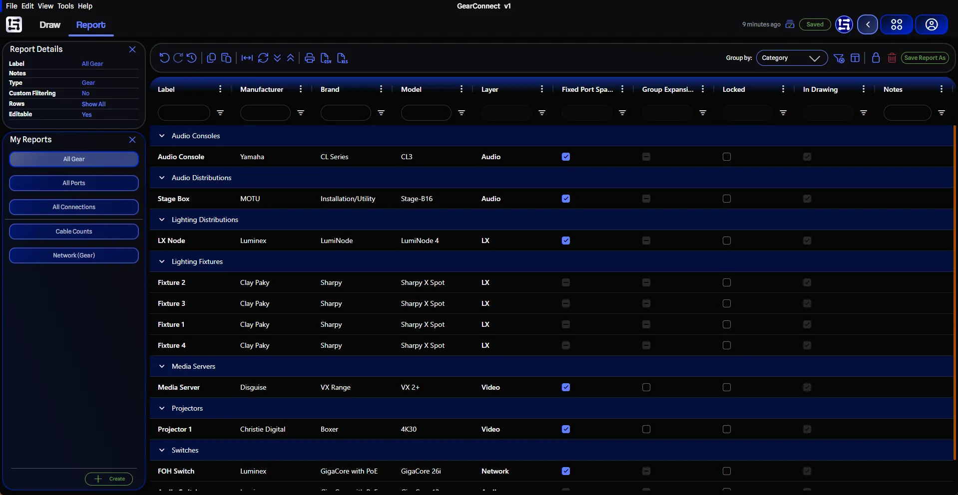
The Report Page offers a way to not only generate custom reports for your project (Pro feature), but also allows you to create custom layouts and views for how to work with your project data (Pro feature). It supports all the expected features of a typical spreadsheet editor such as sorting, filtering, and toggling columns on and off.
All reports are dynamic and will update in real-time as you make changes. If you make changes in the report, they will be reflected back in the drawing as well.
There are three types of reports:
- Gear
- Ports
- Connections
Each report type has different columns and options available to them, along with auto grouping based on gear category or specific gear item. You can save custom reports from the Save Report As button in the toolbar to save any custom filtering, sorting, or column visibility you have set up (Pro feature).
All reports can be exported by printing to a PDF or by exporting to a CSV. Additionally, Pro users can export to Excel.
You can learn more about reports here.
Library Editor (Pro feature)
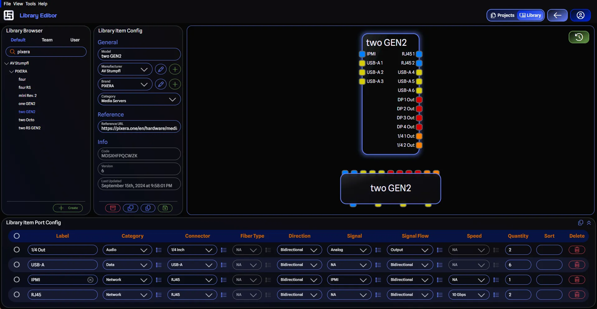
And finally, the Library Editor (accessible from the top navigation button or the View Menu) is where you can create your own custom library items for your personal library or team libraries.
Creating Library Items
You have two ways to create custom library items:
-
Create from Scratch: Click the Create button to start with a blank item. You’ll need to:
- Set up the basic details (model, manufacturer, brand, category)
- Add all ports and configure their properties
- Save your new item
-
Copy and Customize: Browse and select a library item from the default library and copy it to your personal library or a team library using the Copy to… button. From there, you can customize the gear by adding or removing ports, changing their types, signals, quantity and more.
Working with Ports and Labels
By default, a label will be auto-generated for you based on the Connector, Direction, Signal Flow, and Quantity. These auto-generated labels can be viewed in the row itself but also in the live preview of the gear for the Detail Mode version. You can set a custom label if you want to specify it yourself (for example, you want to label it based on signal type instead of the connector).
Live Preview
The live preview will show you what the gear will look like in the drawing in both Detail Mode and Standard Mode. This will auto-update a couple of seconds after you stop making changes, with an improved loading experience showing “Regenerating…” during updates. You can disable this auto-updating by toggling the Disable Auto-Regenerate Preview button at the top right.
Categories
You can change the category of library items (Lighting Consoles, Speakers, Media Servers, etc.) to properly organize your custom gear. Changing the category will create a new version of the item when saved.
You may then archive the previous item if it is no longer needed.
Archiving Items
When you no longer need a library item, brand, or manufacturer, you can archive it using the Archive button. Archived items are removed from the Library Browser which means you cannot add them to projects anymore. But they remain accessible to existing projects that were using them previously.
Versioning
All gear in the library is versioned and independent of specific projects, allowing you to use any item across multiple projects. If you update an item in the library, projects using that item will continue to reference the previous version until you manually update the item within each project.
If you share your project with someone else, when they open the project, your custom library items will be loaded with the project, but they will not be able to edit them. Team library items are shared with all team members and can be edited by members with write access.
