Ports
Ports are the connectors on gear that allow you to connect cables (connections) to other gear.
Each port has a set of properties that define the type of connection that can be made to it, as most properties are used for real-time validation.
This ensures you cannot plug a cable in backwards, or connect incompatible ports together (for example an RJ45 can’t be connected to an XLR port).
Ports in GearConnect come in two forms. The first is the port data that lives on the library items. These are the default values that will be used when you add a piece of gear to a project. The second is the port data that lives on the gear items in a project. These are the values that are used after the gear has been added to a project. You can think of this relationship like a template and an instance of that template.
To explain further, let’s take a look at the properties that make up each type of port.
Library Port Options
Section titled “Library Port Options”Library ports are the default values that are set on the library item and will be used when the gear is added to a project.
- Category: The category of the port (Network, Audio, Lighting, etc.). Supports Multi-Mode.
- Block: An optional identifier for grouping ports into blocks (max 4 alphanumeric characters). This allows you to have multiple groups of identical port configurations on the same gear item. For example, a video switcher with 3 blocks of HDMI outputs could use Block 1, 2, and 3.
- Connector: The connector type of the port (RJ45, XLR 5-Pin, OpticalCon Duo SMF, etc.). Connectors are organized by category for easy selection. Supports Multi-Mode.
- Direction: The physical direction of the port (Input, Output, Bidirectional). This is the physical direction of the pins on the port, if that port can be reversed on a piece of gear. For example, XLRs can be both male and female on the same piece of gear, where most other ports are only ever one physical type (RJ45, BNC, etc.). Most gear will be Bidirectional.
- Signal: The signal type that is sent or received on the port (SDI, sACN, MIDI, etc.). Signal types are organized by category for easy selection. Supports Multi-Mode.
- Signal Flow: The direction the signal is traveling (Input, Output, Bidirectional). This is not the physical direction of the pins on the port, just the flow of data. For example, an SDI BNC port will physically both be the same port direction on the two connecting devices, but the signal flow usually only goes one way. Supports Multi-Mode.
- Speed: On applicable port configurations, you may have a speed setting (For network ports, you may have 1Gbps, 10Gbps, etc.). Supports Multi-Mode.
- Quantity: The number of ports of this type on the gear.
- Start: Custom starting port number. By default, it will be 1 for the first port, but you can override this to have the ports start from a different number. For example, switches that have shared ports, so two ports may share port number 24.
Gear Port Options
Section titled “Gear Port Options”Gear ports are the values that are set on the gear item in a project and are used after the gear has been added to a project. You can see these options are almost identical to the library port options for this reason.
- Connected Gear: The gear item that is connected to this port via a connection.
- Label: The name of the port.
- Category: The category of the port (Network, Audio, Lighting, etc.). These are used mostly for labeling purposes and don’t affect connection validation.
- Block: An optional identifier for grouping ports into blocks (max 4 alphanumeric characters). Useful for port configurations like having Output A and Output B of the same connector. This is not used for validation.
- Connector: The physical connector on the device (RJ45, XLR 5-Pin, OpticalCon Duo SMF, etc.). Connectors are organized by category for easy selection. These determine the colour that appears in the drawing for the port. This is used for validation.
- Direction: This refers to the physical direction of the port, determining how the cable is plugged in, based on pin orientation. For most ports, the direction is bidirectional since most ports, like RJ45 or BNC, have the same male or female port on the device. However, for ports like XLR, which can have different male and female pin directions for inputs and outputs, we use Direction to specify. (Input, Output, Bidirectional). This is used for validation.
- Signal Type: This is the type of signal that will be sent or received from this port (SDI, sACN, MIDI, etc.). Signal types are organized by category for easy selection. This is used for validation.
- Signal Flow: This is the direction of the signal flow. (Input, Output, Bidirectional). This is the not the physical direction of the pins on the port, just the flow of data. For example, an SDI BNC port will physically both be the same port direction on the two connecting devices, but the signal flow usually only goes one way. This is used for validation.
- Speed: For some ports, a speed is also provided. For network ports, this may be 1Gbps, 10Gbps, etc. For SDI ports, this may be HD-SDI, 3G-SDI, etc. This is not used for validation.
- Sort Order: The sort within the port’s grouping. For example, all DMX Outs might be numbered from 1-8 while DMX Ins could be numbered from 1-4. Renumbering DMX In 1 to DMX In 5 would change DMX Ins to be 2-5, while maintaining 1-8 for DMX Outs.
- Expansion Card: (Only available if the port belongs to an expansion card) The library item this
port belongs to. This will be an expansion card that was selected when the gear was added to the project.
- This will also include a number, for example you may see “DisplayPort 1.2 Quad Output (2)” which would indicate that this is the second expansion card of this type that was added to gear.
All categories except switches support IP Addresses if the connector is included in the connector type list here. If so, the port will have the following additional fields:
- DHCP: Whether the port uses DHCP for automatic IP address assignment.
- IP Address: The IP address of the port. Displays “DHCP” in Reports when DHCP is enabled.
- Subnet: The subnet of the port. Displays “DHCP” in Reports when DHCP is enabled.
Using the Categorized Selector
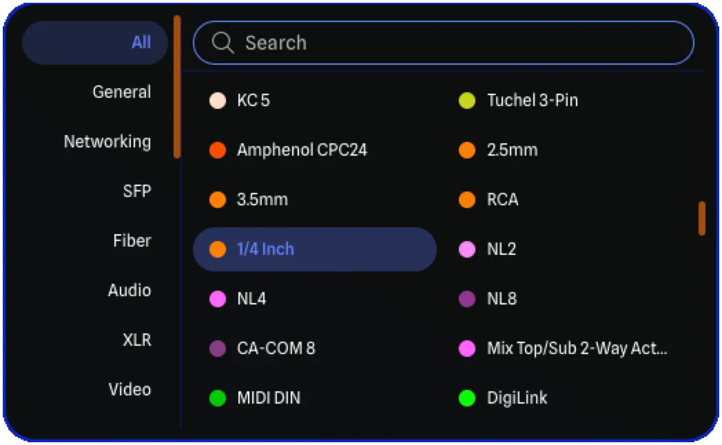
Section titled “Using the Categorized Selector”When selecting a Connector or Signal type for a port, a categorized selector menu appears. This menu is used throughout the app in the Library Editor, Gear Config, and Cable Inventory Manager.
Menu Layout
Section titled “Menu Layout”The selector has two panels:
- Left Panel: A list of categories to filter the available options. Click a category to show only options in that category.
- Right Panel: A search bar at the top, followed by a two-column grid of available options. For connector types, each option displays a color swatch indicating its port colour.
Categories
Section titled “Categories”Select All to view every available option, or choose a specific category to narrow your selection.
For a complete list of all connector categories and their colors, see Port Colours. For signal type categories and compatibility information, see Signal Type Compatibility.
Search and Filter
Section titled “Search and Filter”Type in the search bar to filter options by name. The search filters within the currently selected category, so select All first if you want to search across all options.
Keyboard Navigation
Section titled “Keyboard Navigation”The selector supports full keyboard navigation:
- Arrow Keys: Navigate the two-column grid (Up/Down moves between rows, Left/Right moves between columns).
- Enter: Select the currently highlighted option.
- Type to Search: Start typing to filter options (focus automatically moves to the search bar).
Port Sorting & Reordering
Section titled “Port Sorting & Reordering”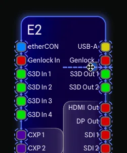
Ports in GearConnect are automatically organized into port groups based on their shared properties and sorted using a default algorithm. This sort order is used both on the drawing and in the Gear Config tables, making it easy to match up the tables with the drawing’s order.
While the defaults work for most gear, you can customize the layout by overriding the side assignment for each group, reordering groups via drag-and-drop on the drawing, or setting custom group order values.
For details on the port table toolbar, group header controls, and bulk editing, see Gear Config > View All Details.
Sort Algorithm
Section titled “Sort Algorithm”Ports have a default sort algorithm that determines the order in which they are displayed on the drawing and in the tables in the Gear Config Pane.
If you have set a custom group order, that takes priority over the default sort. Otherwise, ports are sorted in the following order:
- Direction - Bidirectional ports first, then inputs, then outputs.
- Connector - Grouped by connector type (e.g., RJ45, XLR, HDMI).
- Category - Grouped by category (e.g., Network, Audio, Video).
- Speed - Grouped by speed (e.g., 1 Gbps, 10 Gbps).
When Group Expansion Ports is enabled, regular ports sort before expansion card ports, and ports within each card are kept together. See Gear Config > Expansion Cards for more information.
Port Groups
Section titled “Port Groups”Ports are automatically organized into groups based on their shared properties. These groups are the fundamental organizational unit - individual ports keep their numbers, but entire groups move together. You cannot split a group or move a single port to another group, without changing that port’s options (such as changing the connector or category).
Groups are formed by combining the following properties:
- Category
- Connector
- Direction
- Signal type
- Signal flow
- Speed
- Expansion Card (both the model and card number, if applicable)
For more details on how groups are named and displayed, see Gear Config > Port Groups.
Auto Side Assignment
Section titled “Auto Side Assignment”By default, ports are automatically assigned to sides of the gear item based on their direction. These defaults allow gear to be presented clearly and in a consistent fashion, however you can customize this further if you like.
Detail Gear
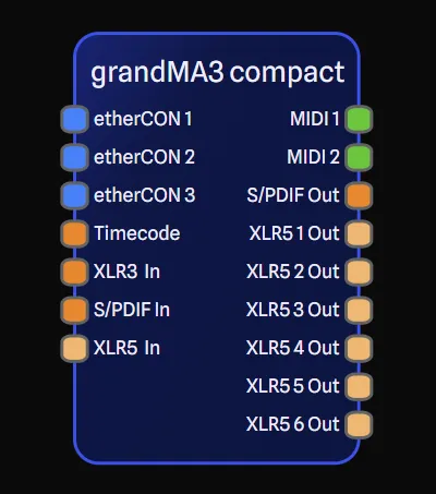
Section titled “Detail Gear”For gear in Detail Mode (left and right sides):
- Bidirectional ports → automatically split between left and right (see below)
- Input ports → left side
- Output ports → right side
Standard Gear
Section titled “Standard Gear”For gear in Standard Mode (top and bottom sides):
- Bidirectional ports → automatically split between top and bottom (see below)
- Input ports → top side
- Output ports → bottom side
Bidirectional Port Splitting
Section titled “Bidirectional Port Splitting”When bidirectional ports are split across sides, the split is based on the number of visible ports in the group - hidden ports are excluded from the calculation. Toggling port visibility recalculates which side each visible port appears on.
- More than 4 visible ports: Split 50/50 between both sides (e.g., 10 visible RJ45 ports = 5 left + 5 right).
- 4 or fewer visible ports: Stay together on one side, alternating between sides across different groups (e.g., 4 RJ45 ports on the left, 4 etherCON ports on the right).
Side Overrides
Section titled “Side Overrides”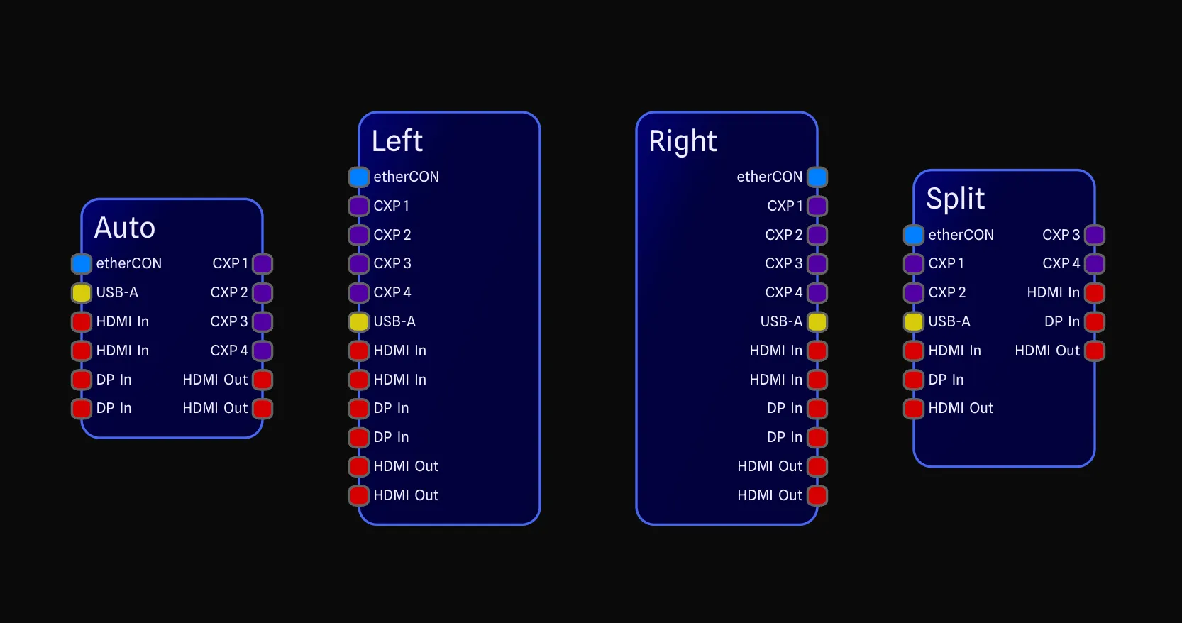
You can manually override which side a port group appears on, bypassing the automatic side assignment.
The available options depend on the gear type:
| Option | Detail Mode | Standard Mode | Behaviour |
|---|---|---|---|
| Auto | ✅ | ✅ | Uses automatic side assignment based on direction. |
| Split | ✅ | ✅ | Forces an even 50/50 split of visible ports across both sides. |
| Left | ✅ | ❌ | Forces all ports in the group to the left side. |
| Right | ✅ | ❌ | Forces all ports in the group to the right side. |
| Top | ❌ | ✅ | Forces all ports in the group to the top side. |
| Bottom | ❌ | ✅ | Forces all ports in the group to the bottom side. |
Side overrides can be applied in several ways:
- Port group header: Click the cycling button on each port group header in the View All Details Dialog to cycle through the available options.
- View All Details Toolbar: Use the Split, Left/Top, or Right/Bottom buttons in the View All Details Dialog toolbar to apply a side override to all groups at once.
- Port Report: Use the Side column dropdown in the Port Report to set the side for each port group.
- Reorder Ports: Dragging a group in the drawing to the opposite side of the gear automatically applies a side override.
- Library Item Port Config: Click the cycling button on each port row in the Library Item Port Config to set default side overrides when gear is added to a project as part of the library item.
- Adding gear: When adding gear in Detail Mode, choosing Left or Right port placement defaults all ports to that side.
To reset all side overrides back to Auto, use the Reset Side Overrides button in the View All Details toolbar.
Custom Group Ordering
Section titled “Custom Group Ordering”
By default, port groups are ordered using the sort algorithm described above. You can override this by customizing the group order:
- Drag handles: Drag a port group header in the View All Details dialog to reorder it within the table.
- Group Order column: Enter a numeric value in the Port Report to set the order directly.
- Reorder Ports: Drag groups to new positions directly on the drawing.
To reset all custom ordering, use the Reset Port Group Ordering button in the View All Details toolbar. This clears all custom values and reverts to the automatic sort.
Reorder Ports on Drawing
Section titled “Reorder Ports on Drawing”
The Reorder Ports mode lets you drag and drop port groups directly on the drawing to customize their order and side placement with immediate visual feedback.
Entering the Mode
Section titled “Entering the Mode”- Selection Toolbar: Select a single gear item and click the Reorder Ports button.
- Right-click menu: Right-click on a gear item and select Reorder Ports.
Visual Feedback
Section titled “Visual Feedback”When the mode is active:
- Each port group receives a dashed outline showing its boundaries.
- Dragging a group lifts it as a semi-transparent image that follows your cursor.
- A dashed drop indicator line shows where the group will be placed.
Dragging Behaviour
Section titled “Dragging Behaviour”- Drag a group vertically (Standard Mode) or horizontally (Detail Mode) to reorder it.
- Cross-side dragging: If you drag a group past the centre line of the gear, the drop indicator switches to the opposite side and a side override is automatically applied.
- When Group Expansion Ports is enabled, dragging an expansion card group moves all groups from that card together as a block.
Exiting the Mode
Section titled “Exiting the Mode”Press Escape, click on an empty area of the drawing, or select a different gear item.
Expansion Cards and Sorting
Section titled “Expansion Cards and Sorting”When Group Expansion Ports is enabled on a gear item, expansion card ports are grouped separately from the rest of the ports. An expansion card cannot be broken up - its port groups always stay together as a unit.
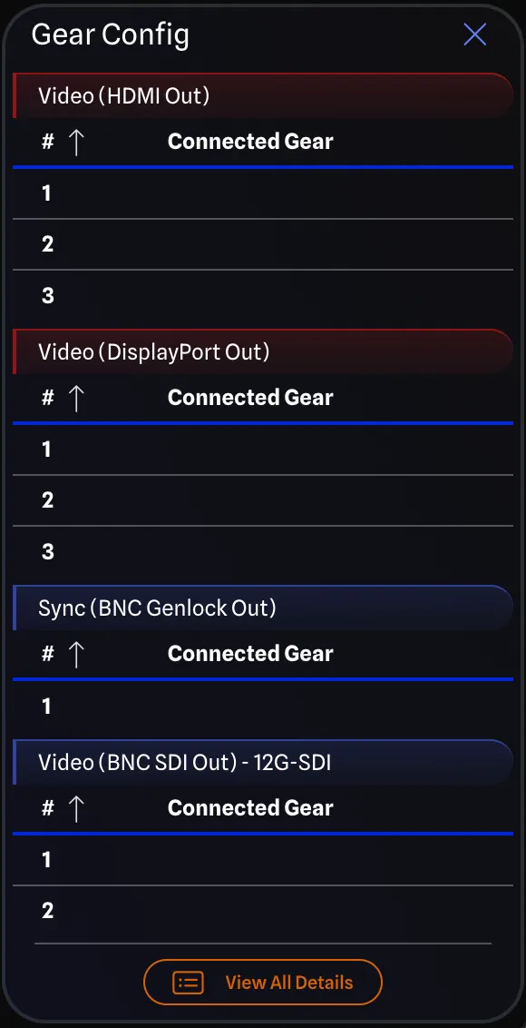
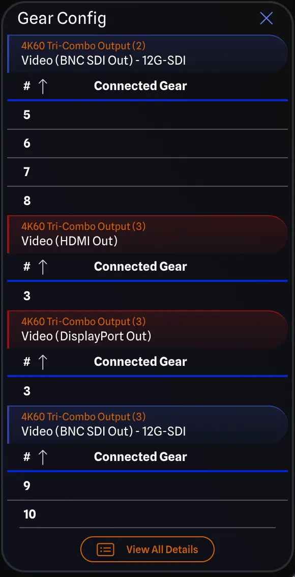
On the left, ports are sorted by type across the entire gear without any expansion card grouping. On the right, the same ports are grouped under their expansion card headers (showing the card model and number in orange, e.g., 4K60 Tri-Combo Output (3)), with each card’s port groups kept together.
What You Can Do
Section titled “What You Can Do”- Reorder groups within an Expansion Card: If an expansion card has HDMI, BNC, and RJ45 groups, you can reorder those groups relative to each other within the card.
- Move an entire Expansion Card: Moving any group from an expansion card moves all of that card’s groups together as a contiguous block.
What You Cannot Do
Section titled “What You Cannot Do”- Drag Expansion Card ports into the regular port section: In both the table and the drawing, expansion card groups cannot be mixed with regular port groups, and vice versa.
- Break up an Expansion Card: If you attempt to set a group order in the Port Report that would separate an expansion card’s groups, the order values are automatically renumbered to keep the card together.
When Group Expansion Ports is disabled, ports mix freely regardless of which expansion card they belong to, and normal grouping rules apply.
Port Placement Options
Section titled “Port Placement Options”On gear in Detail Mode, you have additional options for how you would like the ports to be displayed in the drawing.
By default, ports have a fixed spacing between them and are not grouped by expansion cards.
Fixed Port Spacing
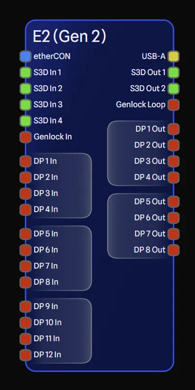
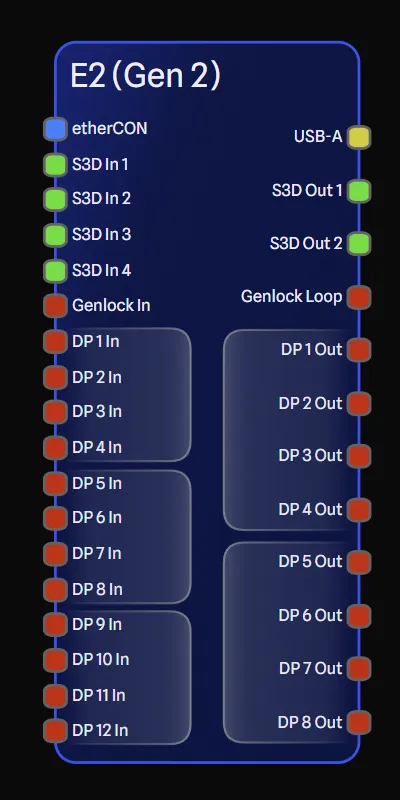
Section titled “Fixed Port Spacing”You can enable or disable this option from the General Settings Pane once you have selected a specific gear item.
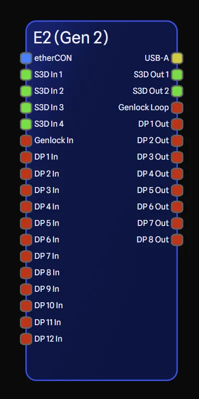
When enabled, ports will have fixed spacing between them (left), starting from the top of the gear item and working down. If you have more inputs than outputs, then you may have empty space at the bottom of the gear item on the output side (or vice versa). Fixed spacing can provide a clean and consistent look to your drawings.
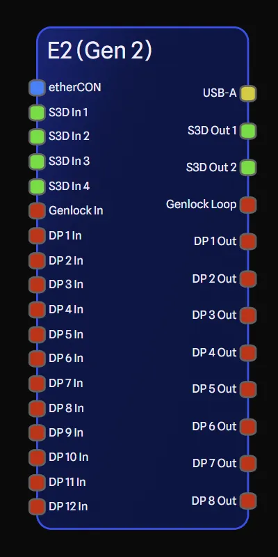
However, you may choose to disable this option, in which case the ports will spread out along each side of the gear item (right). Spacing between ports will be equal distance from each other on the same side of the gear item, but are not necessarily the same spacing relative to the other side or other gear items in your drawing.
Group Expansion Ports
Section titled “Group Expansion Ports”This option allows you to easily see which ports belong to which expansion card.
When enabled, ports that belong to an expansion card will be grouped together and sorted within their expansion card as described above. A coloured rounded rectangle will appear around all ports that belong to the same expansion card. The colour is based on the gear’s Primary Colour property. The size of the rectangle will be automatically calculated based on the size of the gear, and the length of the longest port name on the gear.
If Fixed Port Spacing is enabled, then additional spacing will be added before and after each grouping in the drawing, to help visually separate the expansion cards.
When disabled, all ports will be sorted together as described above, without any grouping or the additional rectangles separating the expansion cards.