App Layout
Here we will go over the layout of the GearConnect app and how to navigate through the different sections.
The GearConnect app is divided into four main pages:
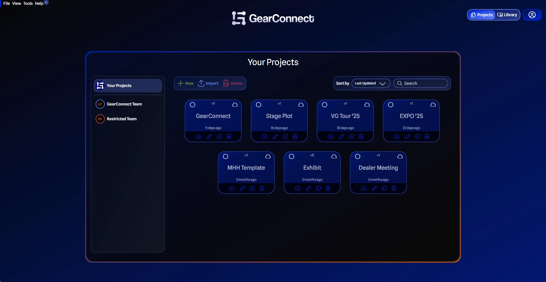
- Project Page: This is the first page you see when you log in. Here you can see all the projects you have created. You can create a new project, edit an existing project, or delete a project.
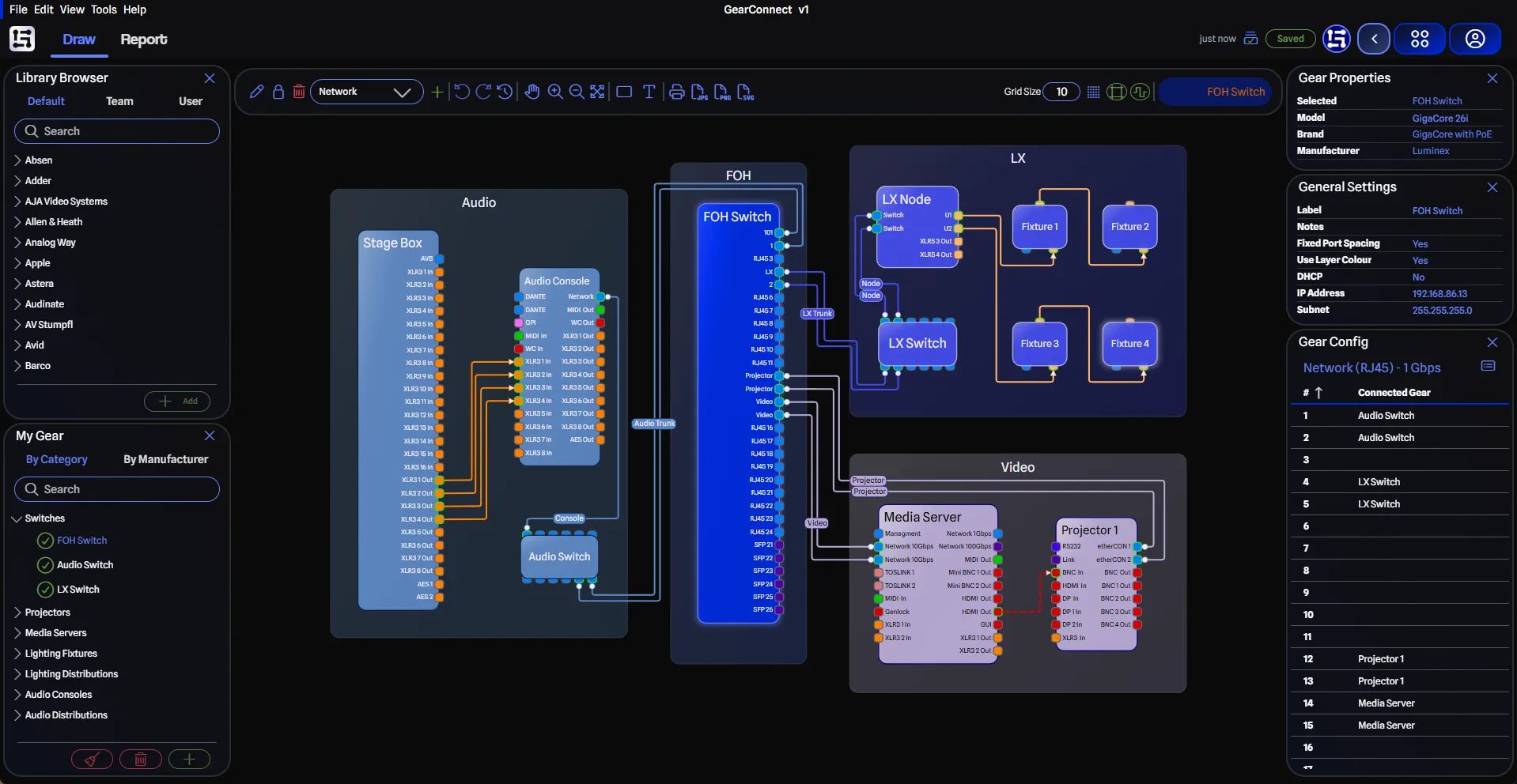
- Draw Page: This is the default page after opening a project. Here you can draw your system drawing, add and edit gear, make connections and more.
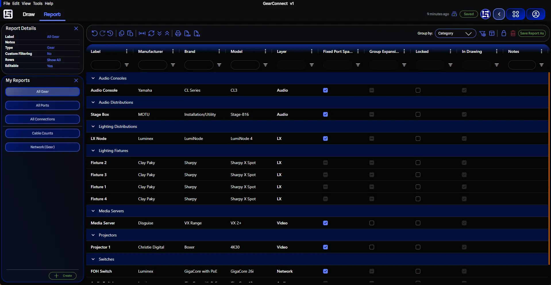
- Report Page: On this project page, you can view and edit all drawing’s data in your project, including gear, ports, and connections. You can also generate and print/export reports from this page as well.
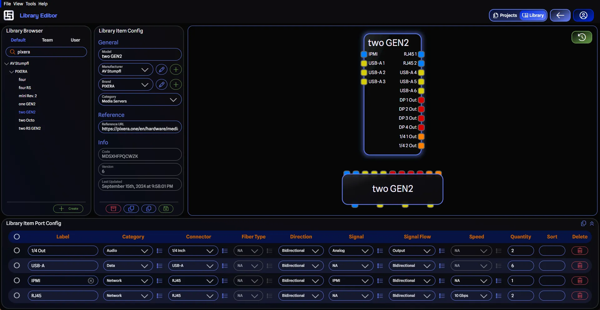
- Library Editor Page: This is where you can view the default library and create your own custom library (Pro feature). You can add and edit gear, their properties, and their ports. Gear created in the Library Editor can be used in all your projects.
On all pages, there is a top menu bar along the top, with common actions. The specific actions will change depending on the page you are on, and they include (from left to right):
- Menu Bar : Common features and actions are available in the menu bar.
- File: This menu contains actions related to projects, including opening, saving, and exporting projects.
- Edit: (Draw and Report Pages only) This menu contains actions related to the current project such as project settings.
- View: This menu contains links to other pages as well as toggles for the various panes.
- Tools: (Draw, Report, and Library Editor pages only) This menu contains app tools such as syncing your project with the server or reloading the library.
- Help: This menu contains actions related to the app, such as viewing the changelog, keyboard shortcuts, or the about information.
- Navigation Selection: This contains a link to the Project Page and the Library Editor Page. It will highlight the current page you are on, and collapse to an arrow you can expand when on other pages.
- Go Back: When on the Library Editor page, this button will take you back to the previous page (for example, your most recent project, the Team Settings page, etc.).
- User Info: This is where you can view and edit your user information, manage your subscription, and log out.
Project Page

From this page, you can:
- Create a new project by clicking the New button.
- Import a project by clicking the Import button (Pro feature).
- Search existing projects by typing in the search bar.
- Sort projects by Last Updated (default) or Name by clicking on the Sort by dropdown.
- Rename a project by clicking on the pencil icon.
- Delete a project by clicking on the trash icon.
Opening a Project
To open a project, simply click on the project card. This will take you to the Draw Page of the project.
Alternatively, you can press the Hard Load Project button (or hold CTRL and click on the project card)
to skip loading the project from the latest version history and instead load the project from the server.
Draw Page

This page has two main sections:
- Drawing Area: This is where you draw your system drawing. You can add and edit gear, make connections, and move around the drawing here. The Drawing Toolbar is located at the top of the drawing area.
- Panes: These are the sidebars on the left and right of the drawing area. You can toggle these panes on and off using the View menu.
Drawing Area
The Drawing Area is where you draw your system drawing. You can add and edit gear, make connections, and move around the drawing here. This will be the layout you spend most of your time in when using the app. Familiar controls such as middle-click or right-click to pan, and the scroll wheel to zoom in and out are available. You can select gear by clicking on them, and move them around by dragging them.
Moving Around the Drawing
You can move around the drawing by clicking and dragging the background using the middle or right mouse button. If you hold down the Ctrl key
you can pan the drawing by clicking and dragging with the left mouse button.
Alternatively you can also pan the drawing by using the arrow keys on your keyboard. If you hold down the Shift key while pressing the arrow keys,
you will pan faster.
Zooming In and Out
You can zoom in and out of the drawing by using the scroll wheel on your mouse or using the Ctrl+= and Ctrl+- keyboard shortcuts.
Pressing Z will zoom the drawing to fit the screen.
When zooming from the mouse wheel, the zoom will be centered on the mouse cursor. When zooming from the keyboard shortcuts, toolbar, or menu buttons, the zoom will be centered on the drawing area.
Selecting Gear
You can select gear by clicking on them either in the drawing or the My Gear Pane. When selecting gear from the My Gear Pane, the gear will be selected in in the drawing and the item will be centered in the view.
You can clear your current selection by either clicking on the background or pressing the Esc key.
Drawing Toolbar
The Drawing Toolbar contains several helpful tools to help you with your drawing including:
- Edit the label of the currently selected item.
- Align multiple selected items. Learn more here.
- Lock the currently selected item from further edits (and unlock it).
- Remove the currently selected item from the drawing.
- Layer dropdown to view the active layer when nothing is selected, or to view the selected item’s layer when an item is selected. You can change the active layer and the current selection’s layer from this dropdown. Learn more about layers here.
- Add layer button to quickly add a new layer to your drawing.
- Undo and redo recent changes. Learn more here.
- Toggle pan mode on and off.
- Zoom in and out of the drawing.
- Zoom to fit the drawing.
- Draw a Gear Group in the drawing. Learn more here.
- Draw a Text Box in the drawing. Learn more here.
- Toggle Node Edit Mode for editing connection nodes. Learn more here.
- Print the drawing to a PDF.
- Export the drawing to JPG, PNG, and Pro users can export SVG.
- Change the grid size.
- Toggle the grid on and off.
- Toggle the snap lines on and off.
- Enable or disable the Smart Routing feature for connections. Learn more here.
And finally, it displays the name of the selected item, or the total count when multiple items are selected.
You can learn more about the Drawing Toolbar here.
Panes
The Draw Page has the following panes:
- Library Browser Pane: This is where you can view and add gear to your drawing. You can search the default library or your custom library if you are a Pro user. Learn more.
- My Gear Pane: This is where you can view all gear that you have added to your drawing. When you remove gear from the drawing, it will be marked as unused, but still available in your project. You can completely remove it from your project using the Delete button. Learn more.
- Gear Properties Pane: This is where you can view the properties of the selected gear including manufacturer, brand and expansion cards (by clicking on the Model field). Learn more.
- General Settings Pane: This is where you can view and edit the general settings of the selected gear, including the name, notes, colour, and any gear specific settings. For example, a switch allows you to change the IP address and subnet. Learn more.
- Gear Config Pane: This is where you can view all the port details of the selected gear. This is a quick way to see which ports
are connected and to what other pieces of gear. From here, you can click on View all details (or use the keyboard shortcut
Ctrl+Don Windows orCmd+Don Mac) to view all the port details, and edit their properties (Pro feature). Learn more.
Report Page

This page has two main sections:
- Spreadsheet Area: The rows, columns, and cells where you can view and edit your project data. The Report Toolbar is located at the top of the spreadsheet area.
- Panes: These are the sidebars on the left of the spreadsheet area. You can toggle these panes on and off using the View menu.
Spreadsheet Area
The Spreadsheet Area is where you can view and edit all drawing data in your project, including gear, ports, and connections. All the familiar spreadsheet controls are available, such as selecting multiple cells, copying and pasting, and sorting columns. You can learn more here.
Report Toolbar
The Report Toolbar contains several helpful tools while working with your data including:
- Undo and redo recent changes.
- Copy the selected data, also accessible via
Ctrl+CorCmd+Con Mac. - Paste the copied data, also accessible via
Ctrl+VorCmd+Von Mac. - Automatically size the columns to fit the data.
- Reset the column size to the default size (the size of your window).
- Expand all the row groups in the spreadsheet (for gear reports, the groups will be gear categories, and for port and connection reports, gear items).
- Collapse all the row groups in the spreadsheet.
- Print the current report to a PDF.
- Export the current report to CSV and Pro users can export Excel.
- Toggle Full Edit Mode (Port reports only – learn more about report types here).
- Change how the report is grouped with options varying by report type.
- Hide duplicate rows based on currently visible columns.
- Choose which columns to display and their order via a selection dialog.
- Lock or unlock the selected report from further edits.
- Clear all changes to the selected report and revert to the last saved version (this includes any changes made to columns, filters, sorting, etc.).
- Save the selected report, either as the current report (for non-stock reports) or as a new report (for stock reports and non-stock reports).
You can learn more about the Report Toolbar here.
Panes
The Report Page has the following panes:
- Report Details Pane: This is where you can view and edit the details of the selected report, including the label and notes. Learn more.
- My Reports Pane: This is where you can view all the reports in your project. The top three are the stock reports, which are:
- All Gear: This report shows all the gear in your project.
- All Ports: This report shows all the ports in your project.
- All Connections: This report shows all the connections in your project.
These reports cannot be deleted or edited, but they can be saved as a new report, which will then be savable and editable (Pro feature). Your custom reports will be listed below the stock reports. Learn more.
Library Editor Page

This page contains four main sections:
- Preview Area: This is where you can view the gear you have selected along with any changes you have made.
- Library Browser Pane: This is where you can view and select gear from the default library or your user library.
- Library Item Config Pane: This is where you can view and edit the properties of the selected gear, including the name, manufacturer, and brand.
- Library Item Port Config Pane: This is where you can view and edit the ports of the selected gear. You can add, edit, and remove ports from here.
Preview Area
This is a non-interactive area where you can view the gear you have selected along with any changes you have made. You may zoom and pan in this area to get a better view of the gear.
Updates will be shown approximately half a second after you make them. You can toggle the auto-update feature by clicking on the Disable/Enable Auto-Regenerate Preview button on the top right of the preview area. When active, the button will be green.
Library Pane
This is the same as the Library Browser Pane on the Draw Page, but you can’t add gear to your drawing from this pane. Once a library item is selected, the preview and selection details will be shown in the Preview Area and Library Item Config Pane and the ports will be shown in the Library Item Port Config Pane. Learn more.
Library Item Config Pane
Here is where you can view and edit the properties of the selected gear, including:
- Model: The name of the gear.
- Manufacturer: The manufacturer of the gear. You can edit or add a new manufacturer by clicking on the pencil or plus buttons.
- Brand: The brand of the gear. You can edit or add a new brand by clicking on the pencil or plus buttons.
- Reference: An optional URL to the gear’s data sheet, website, or any other reference material that would be useful to reference in the drawing.
Non-editable fields include the unique Code, the Version of the gear, and the Last Updated date. Learn more.
Library Item Port Config Pane
The bottom section of the Library Editor page is where you can view and edit the ports of the selected gear. You can add, edit, and remove ports from here. There are several options for each port including:
- Category: The category of the port (Network, Audio, Lighting, etc.). Supports Multi-Mode.
- Connector: The connector type of the port (RJ45, XLR 5-Pin, OpticalCon Duo SMF, etc.). Connectors are organized by category for easy selection. Supports Multi-Mode.
- Direction: The physical direction of the port (Input, Output, Bidirectional). This is the physical direction of the pins on the port, if that port can be reversed on a piece of gear. For example, XLRs can be both male and female on the same piece of gear, where most other ports are only ever one physical type (RJ45, BNC, etc.). Most gear will be Bidirectional.
- Signal: The signal type that is sent or received on the port (SDI, sACN, MIDI, etc.). Signal types are organized by category for easy selection. Supports Multi-Mode.
- Signal Flow: The direction the signal is traveling (Input, Output, Bidirectional). This is not the physical direction of the pins on the port, just the flow of data. For example, an SDI BNC port will physically both be the same port direction on the two connecting devices, but the signal flow usually only goes one way. Supports Multi-Mode.
- Speed: On applicable port configurations, you may have a speed setting (For network ports, you may have 1Gbps, 10Gbps, etc.). Supports Multi-Mode.
- Quantity: The number of ports of this type on the gear.
- Sort: Custom sort order for the starting port. By default, it will be 1 for the first port, but you can override this to have the ports start from a different number. For example, switches that have shared ports, so two ports may share port number 24.
You can also copy and paste ports between library items for faster editing. If you have a lot of ports on a single library item, you can expand this pane to full screen by clicking on the Expand button on the top right of the pane. Learn more.

