Connections
A connection is the link that connects two of ports together. It usually represents a physical cable that connects two devices together. In GearConnect this is shown as a line between two ports.
Properties
Each connection has several properties that define how it works:
-
Source Port: The port where the connection starts. This determines which layer the connection is on (you can change it the layer after) and is the port where you first start drawing the connection from.
-
Target Port: The port where the connection ends.
-
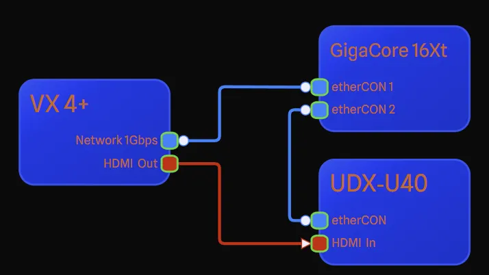
Direction: The direction of the connection (input, output, or bidirectional). This is determined by both the port direction and the signal flow properties of the ports. The signal flow is used first, if it’s not set, the port direction is used. Depending on the direction, you will see different icons on the connection line (see example above):
- Circle: This end of the connection is bidirectional. Depending on what you are working on, most connections will have a circle on either end to signify that both ends are connected to bidirectional ports.
- Arrow: This end of the connection is an input. The signal flows from the other end of the
connection to this end.
- No Icon: This end of the connection is an output. The signal flows from this end of the connection
to the other end.
You can also optionally enable animated signal flow indicators on directional connections from Project Settings.
-
Adapter Required: Based on the connector validation, the app will determine if an adapter is needed. For example, connecting an XLR3 to XLR5 is possible, but you will need an adapter to do so. In this situation, you will see a dotted line instead of a solid line to signify that an adapter is needed.
-
Signal Warning: Similar to the adapter required, the app will determine if there is a signal mismatch. For example, sending HDMI to an SDI port will cause a signal mismatch. In this situation, you will see the same dotted line as the adapter required to alert you that there is a signal mismatch.
-
VLANs Matching: If both ports have VLANs, the app will check if they match. If they don’t, you will get a notification that the VLANs don’t match but you will not see a dotted line.
-
Colours: The connection will have a primary and secondary colour. The primary colour is the colour of the line itself, where the secondary colour is the colour of any label borders added to the connection. You can customize the colours in the following ways:
- Use Port Colour: This is the default and will use the colour of the source port.
- Use Layer Colour: This will use the colour of the layer the connection is on.
- Use Custom Colour: You can ignore both the port and layer colours and set your own custom colours.
Validation
When you make a connection between two pieces of gear, the app makes sure the connection is valid. This happens in real-time so you get instant feedback, helping ensure that your setup works as expected and catches mistakes early in the process.
See Real-Time Port Compatibility for how this feedback is displayed while drawing connections.
You can also disable this validation if you wish by using ports with the Generic Connector, which most of the gear in the generic category uses, or using Full Edit Mode (Pro feature), you can change any port to a Generic Connector.
When validation happens, it goes through the following checks:
- Loopback: The app prevents connections that try to connect back to itself.
- Duplicate: Neither port can already have an existing connection on it.
- Connector: Checks if the Connectors (the connector) on the two ports are compatible. If they’re not directly compatible, it checks if an adapter can be used to make them work together. If an adapter is needed, the app shows a dotted line instead of a solid line. If the connection is still not possible, the app will not allow you to make the connection.
- VLAN: If both ports use Virtual LANs (VLANs), the app checks that they are the same. This will not prevent the connection from being made, but it will issue a warning if they don’t match.
- Directions: Checks that the is a valid direction between the two ports by checking for
any of the following:
- Input to Output: One port must be an input and the other an output.
- Output to Input: One port must be an output and the other an input.
- Bidirectional to Anything: A bidirectional port can connect to any direction.
- Anything to Bidirectional: Any direction can connect to a bidirectional port.
- Signal Type: Checks if the signal types are compatible if they are present (not all ports have signal types). If there’s a potential mismatch that might cause problems, it issues a warning with a dotted line.
- Signal Flow: The app ensures that the signal flow (the direction the signal travels) is
correct. This logic is the same as the Connector logic, it will accept the connection
so long as any one of the following is true:
- Input to Output: One port must be an input and the other an output.
- Output to Input: One port must be an output and the other an input.
- Bidirectional to Anything: A bidirectional port can connect to any signal flow.
- Anything to Bidirectional: Any signal flow can connect to a bidirectional port.
If these all pass, the connection is allowed to be made. Some of these may issue a warning, and some may prevent the connection from being made. Generic Connectors will skip most of these checks, but these checks are always performed:
- Loopback
- Duplicate
- VLAN
Real-Time Port Compatibility
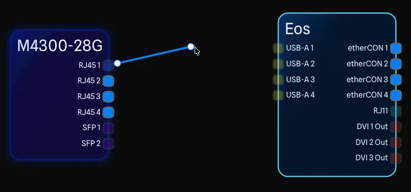
While drawing a connection, ports display real-time compatibility indicators to help you identify valid connection targets. As you drag a connection from a source port, incompatible ports on the drawing will gray out, making it easy to see which ports can accept the connection.
This uses the same validation logic described above, providing immediate feedback before you complete the connection rather than only after the connection is made.
Smart Routing
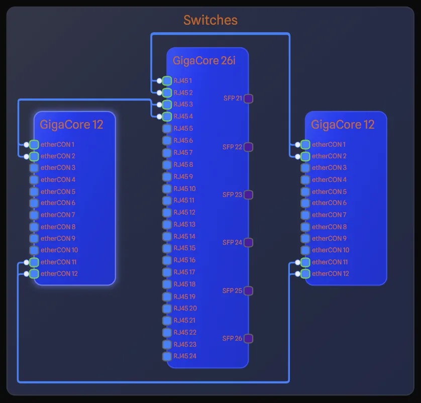
One of the unique features of GearConnect is the Smart Routing feature. In most drawing applications, you need to manually adjust connections and lines to avoid gear and obstacles. With Smart Routing, connections will automatically route around gear items and other obstacles.
There are times when smart routing cannot find a path, such as when gear items are too close together. In these times, the connection will fall back to a simple straight line. You can toggle Smart Routing on and off by clicking the Disable Smart Connection Routing or Enable Smart Connection Routing button in the Draw Toolbar.
Manual Routing
You can manually route connections by adding nodes that the connection path will follow. When Smart Routing is enabled, the app will take your placed nodes into account when calculating the route.
Ways to Access
There are three ways to edit nodes on a connection:
- Node Edit Mode - Enable this mode from the Draw Toolbar to edit nodes on any connection. See Node Edit Mode below for details.
- Selection Toolbar - Select a single connection and click Edit Nodes in the Selection Toolbar to edit nodes on that specific connection.
- Edit Menu - Select a connection and use Edit > Connections > Edit Nodes from the Edit Menu.
Once in node editing, click on the connection line to add a node, then drag it to position the route. Double-click a node to remove it. To clear all nodes at once, use Remove All Nodes from the Selection Toolbar, the right-click menu, or the Edit Menu.
Node Edit Mode
Node Edit Mode provides a dedicated mode for editing connection nodes. When enabled via the toggle button in the Draw Toolbar, you can click directly on connections to add, move, or remove nodes without accidentally selecting other items.
To enable Node Edit Mode, click the Node Edit Mode button in the Draw Toolbar. The button will highlight and the cursor will change to a crosshair to indicate the mode is active. Click it again to disable the mode.
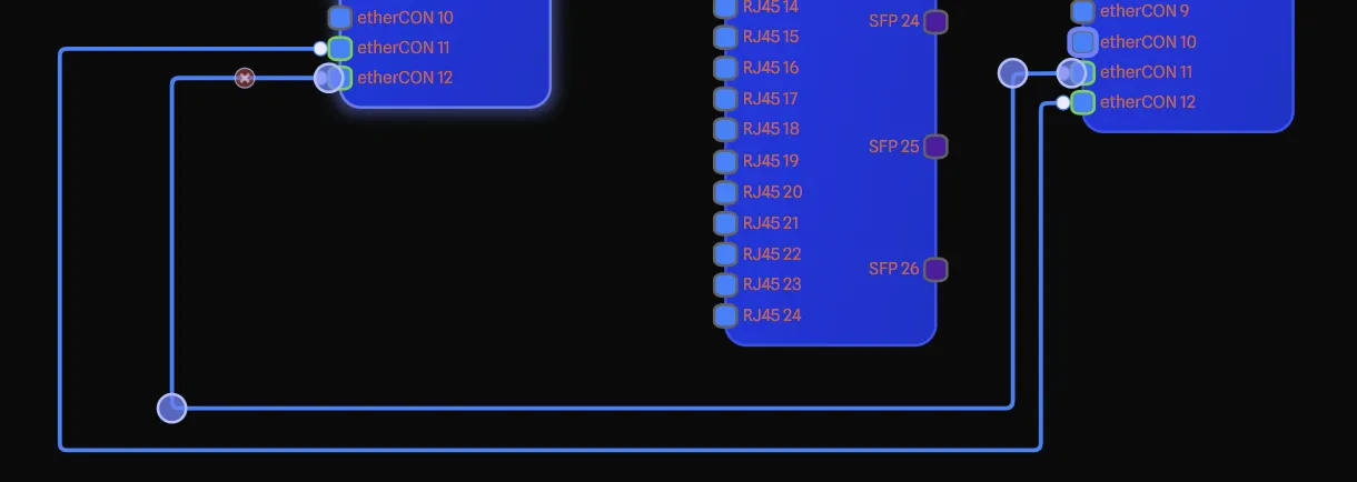
Moving Connections
When you hover over a connection, you will see a all the nodes on the connection. This includes the source and target ports. You can click and drag the connection to move it to a new connection. When you move a connection, the validation will be re-run to ensure that the connection is still valid. If not, the connection will be removed.
Connection Colours
You can change the colours of the connection by right-clicking on the connection and selecting Edit Colours. You have the options defined above for the primary and secondary colours, with the default being Use Port Colour.
When using the Use Custom Colour option, you also have the same Base on Primary Colour option as with layers. This will set the secondary colour to be 15% lighter than the primary colour.
Changing Layers
You can change a connection’s layer by selecting it and using the layer dropdown in the Draw Toolbar. When multiple connections and gear are selected, you can change the layer for all of them at once (requires Local Mode).
If a connection uses layer colours, the colours will automatically update to match the new layer.
Connection Labels
You can add a label to the connection by right-clicking on the connection and selecting Add Label. This will open a dialog for you to enter the label text. You can also edit the label by right-clicking on the connection and selecting Edit Label.
Once a label has been added, you can click and drag it along the line to position it where you want.
Bulk Create Connections
When you need to create multiple connections between two pieces of gear with compatible ports, you can use the Bulk Create Connections feature to save time.
Ways to Access
There are four ways to access bulk connection creation:
- From the Selection Toolbar: Select a connection and click Bulk Create Connections in the Selection Toolbar.
- From the context menu: Right-click on an existing connection and select Bulk Create Connections.
- From the Edit Menu: Select a connection and use Edit > Connections > Bulk Create Connections from the Edit Menu.
- While creating a connection: Hold
Ctrlwhen releasing the mouse button after drawing a connection. This will create the connection and immediately open the Bulk Creation Dialog.
Using the Feature
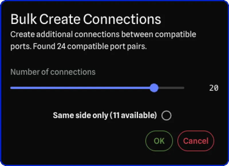
When you open the Bulk Creation Dialog, it will scan for additional compatible port pairs between the source and target gear. The dialog shows:
- The maximum number of compatible port pairs found
- A slider to select how many connections to create
- A Same side only checkbox that limits connections to ports on the same side as the original connection. The checkbox shows how many same-side port pairs are available. When checked, the slider maximum adjusts to reflect only the same-side ports. This option is disabled when all compatible ports are already on the same side.
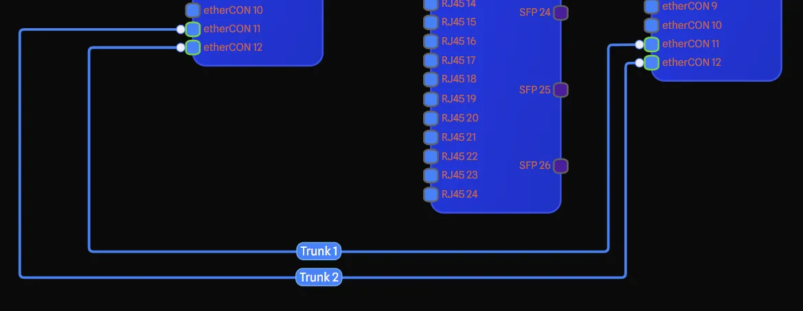
How Ports Are Matched
Ports are matched by first prioritizing ports on the same side as the original connection, then ports on the opposite side. Ports are then sorted by their Sort Order.
For example, if you connect port 1 on the source to port 2 on the target, bulk creation will match the remaining ports in order: port 2 to port 1, then port 3 to port 3, and so on.
When Same side only is checked, ports are matched only if they are on the same side as the original connection. For example, if the original connection goes from the right side of the source gear to the left side of the target gear, bulk creation will only use right-side ports on the source and left-side ports on the target.
The feature uses the same port compatibility rules as regular connections, so all created connections will be valid.
Deleting Connections
You can delete a connection in the following ways:
- Select the connection and click Remove in the Selection Toolbar.
- Right-click on the connection and select Remove.
- Select the connection and press
Backspace.
Multi-Selection
Connections can be included in multi-selection along with other items. Hold Shift and click on connections to add them to your selection. When selected with other items, you can use the Selection Toolbar to perform bulk actions.