

Gear Ports
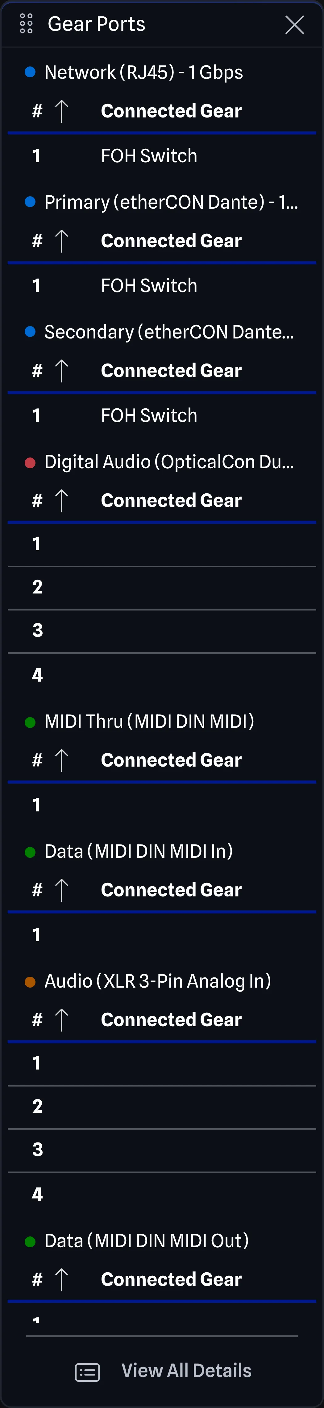
The Gear Ports Pane displays the selected gear’s port details as compact port group tables, with a View All Details button at the bottom of the pane. When every port on the gear is hidden, the pane shows No visible ports to display.
Port Groups BETA APP
Section titled “Port Groups ”GearConnect will automatically create port group labels based on all the port data, as defined in Gear Port Options. These port groups are then used to organize the ports in the Gear Ports Pane and the full details table.
Ports are grouped by combining their properties:
- Category
- Block
- Connector
- Direction
- Signal type
- Signal flow
- Speed
- Is expansion port
- Expansion card model*
- Expansion card index*
These attributes are merged to create group names using this structure:
<Category> (<Connector><Signal Type><Direction>) - <Speed> Block <N>Additionally, when Expansion Groups is enabled, expansion ports will further be grouped using:
<Expansion Card Model> (<Expansion Card Index>)Any ports that do not have a value for a specific attribute will simply be omitted from the group name.
If the port belongs to a block, the block identifier is appended to the group name. For example:
- Network (RJ45) - 1 Gbps Block 1
If the connector is the same as the signal type (for example HDMI) then the signal type will be omitted from the group name.
For example:
- Network (etherCON) - 1 Gbps
- Video (Mini BNC SDI Out)
Each port group header is colour-coded to match the port colour of the connector, and the same colours appear on the ports in the drawing.
If you change any of the port options using something like Full Edit Mode (Pro feature), then the ports will be re-generated from their current configuration. Because of this, you will see ports move around between groups.
Expansion Cards BETA APP
Section titled “Expansion Cards ”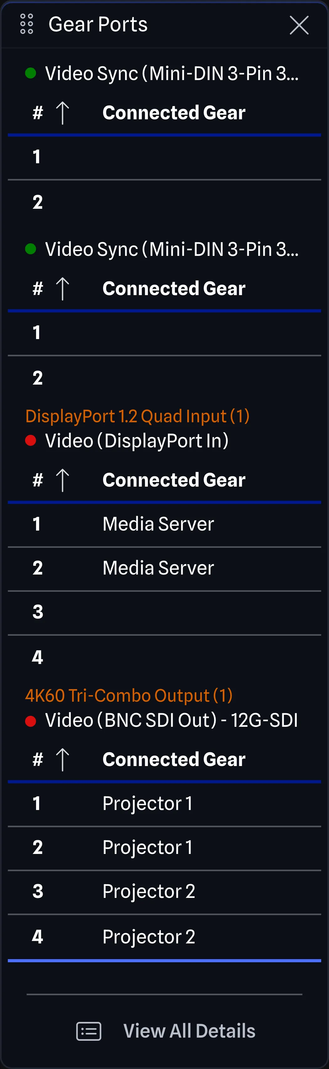
For Detail Mode gear that has expansion cards, and the gear item has Expansion Groups enabled, the ports will be sorted into expansion card tables at the bottom of the Gear Ports Pane. This will group the ports by their expansion card, and then by their port group as described above.
For example, if you have an expansion card that has 4 HDMI ports and 4 DisplayPort ports, you will see two tables at the bottom of the Gear Ports Pane. The expansion card header for both will show the card model and index (e.g., “4K60 Tri-Combo Output (1)”). Below that, the port group name (e.g., “Video (HDMI Out)”) is shown as normal.
The second table will have the same expansion card header but a different port group name (“Video (DisplayPort Out)”). This indicates that both of these tables are part of the same expansion card but have different port groups.
If Expansion Groups is disabled or the gear item does not have expansion cards, instead the ports will be grouped together, ignoring the expansion card details. In the above example, the 4 HDMI and 4 DisplayPort ports would join any other ports on the gear item or other expansion cards in one HDMI out and one DisplayPort out table.
Compact Mode BETA APP
Section titled “Compact Mode ”When the port groups are shown in the Gear Ports Pane, they are in compact mode. This just shows:
- # (the port’s sort order within its group)
- Connected Gear
You can edit the sort order by clicking on the number. This will sort the port within the port group so that all ports of the same type are together in the drawing. This is also why you will see each port group usually defaults to starting from 1 each time.
View All Details
Section titled “View All Details”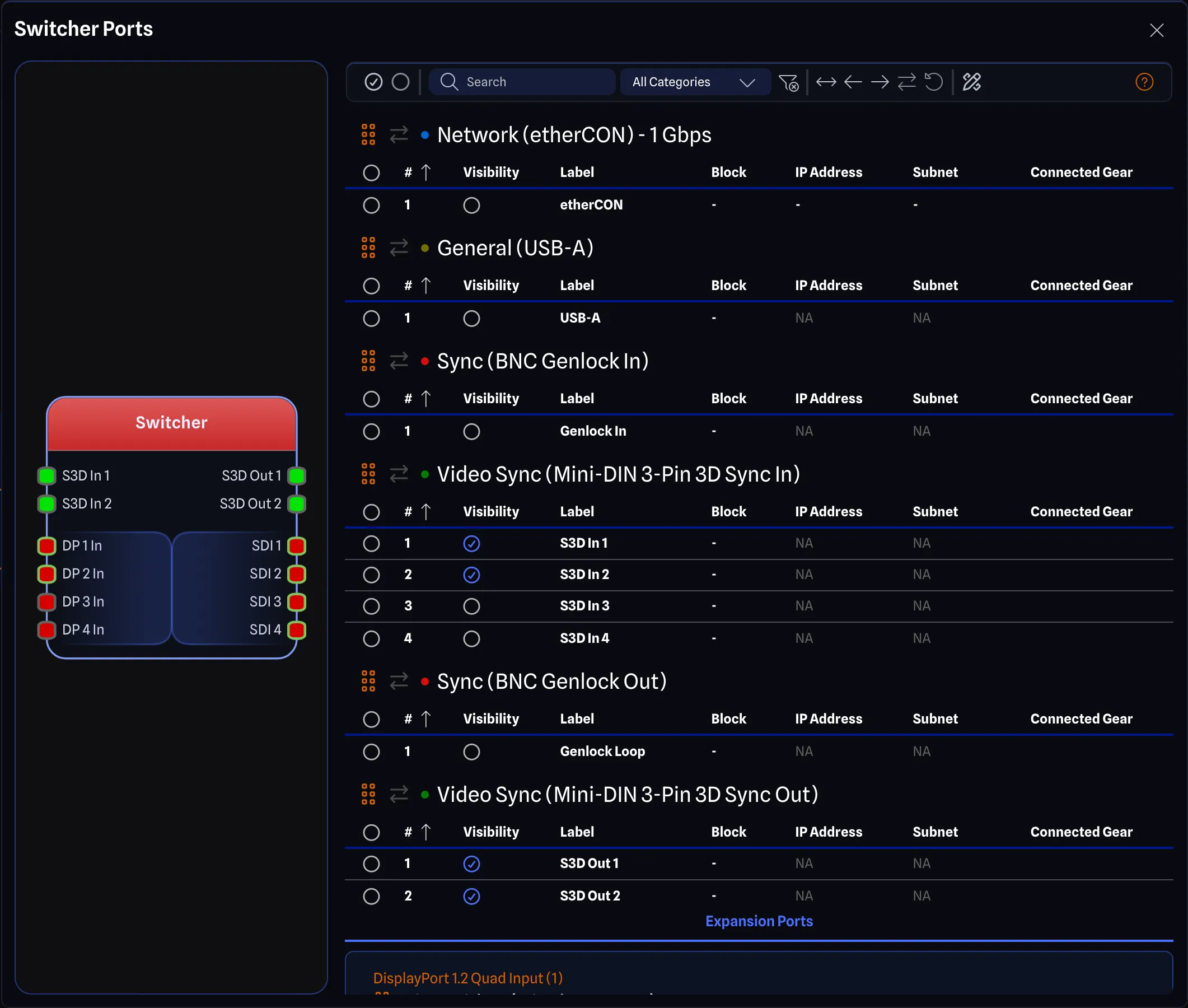
By clicking on the View All Details button at the bottom of the pane, or by using the keyboard shortcut
Ctrl+D (or Cmd+D on Mac), a dialog will open showing all the port details for the selected gear item, with
further information about each port. The dialog is titled with the gear item’s label followed by Ports.
Gear Preview
Section titled “Gear Preview”A live preview of the selected gear item is displayed alongside the port tables. The preview updates in real-time as changes are made to ports, such as toggling visibility, reordering, or editing port options.
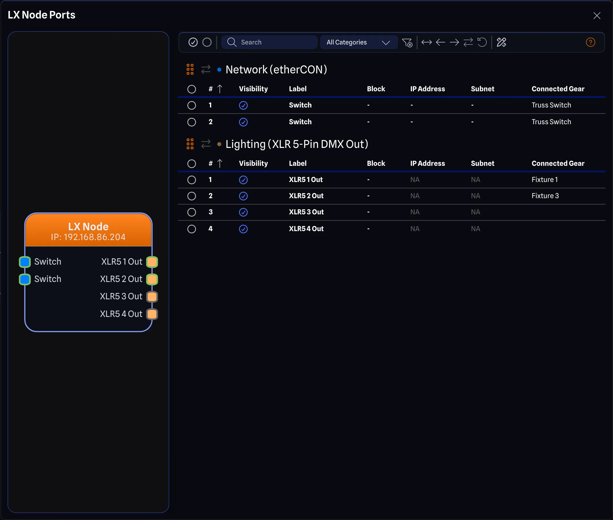
- For Detail Mode gear, the preview appears as a panel on the left side of the dialog.
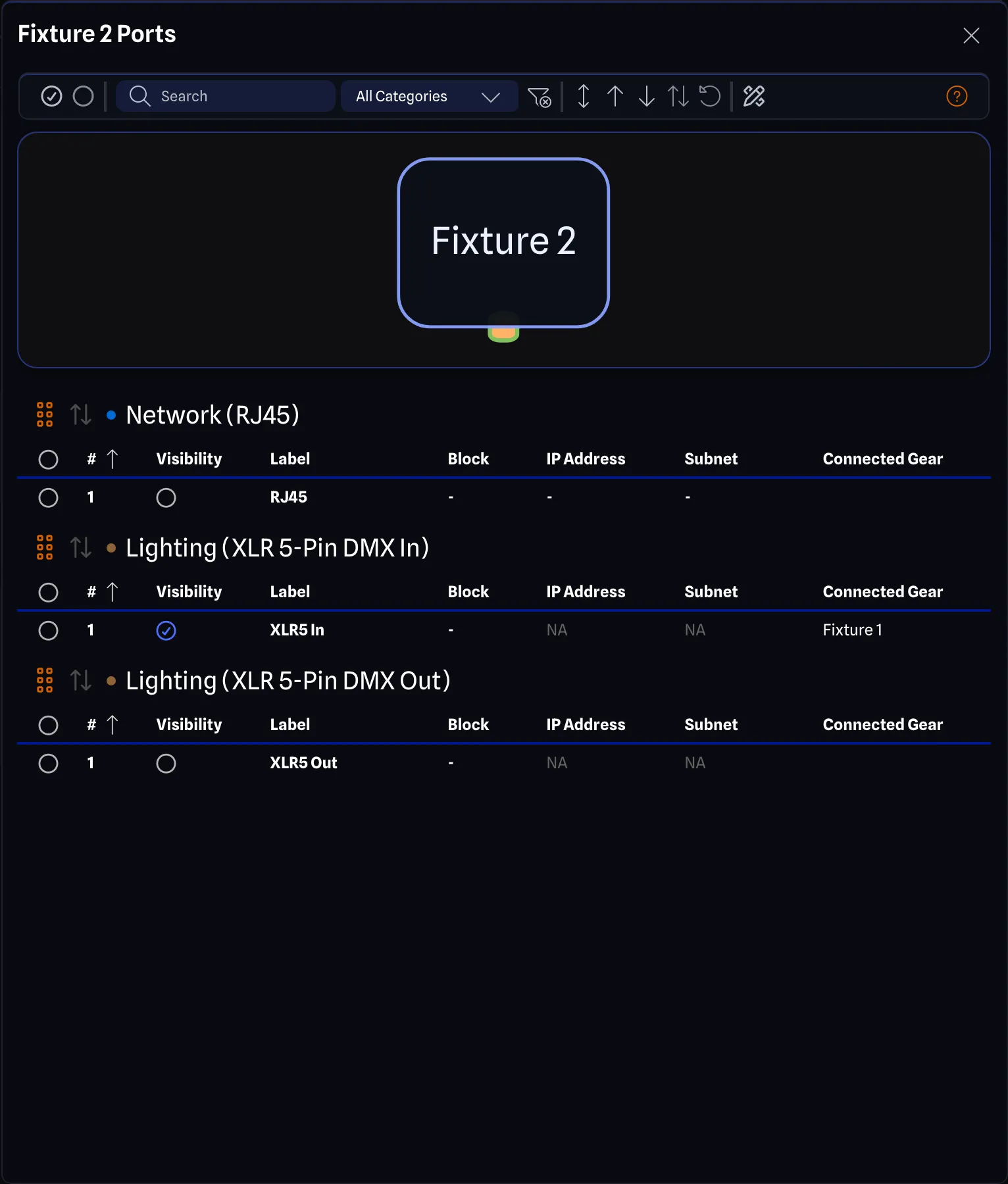
- For Standard Mode gear, the preview appears as a strip across the top of the dialog.
Information shown by default:
- # (the port’s sort order within its group)
- Visibility
- Label
- Block
- IP Address (network ports only, applicable to all gear except for Switches)
- Subnet (network ports only, applicable to all gear except for Switches)
- VLAN (Switches only)
- Connected Gear
# and Connected Gear work the same way as they do in compact mode. The port option columns, such as Category, Connector and Signal Type, appear only where a port offers a choice, see Full Edit Mode.
Visibility is a checkbox to show or hide the port in the drawing. This is useful for when you are done adding connections to a gear item and do not need to see the rest of the ports.
Toolbar BETA APP
Section titled “Toolbar ”
There is a toolbar at the top of the dialog with the following options:
- Select All Ports: Selects all ports across all port tables.
- Deselect All Ports: Deselects all currently selected ports across all port tables.
- Search: Filter port groups by searching across group titles, expansion card names, and port labels.
- Filter by Category: Filter the displayed ports by a whole category or by one connector. The filter uses the categorized selector, where each category starts with an All option, such as All Video, and All Categories turns the filter off.
- Show Connected Ports Only: Toggle to show only ports that have active connections. With the toggle on, the button shows Show All Ports and turns the filter back off.
- All Sides: Split: Apply a Split side override to all port groups, splitting them evenly across both sides.
- All Sides: Left / All Sides: Top: Force all port groups to the left side (Detail Mode) or top side (Standard Mode).
- All Sides: Right / All Sides: Bottom: Force all port groups to the right side (Detail Mode) or bottom side (Standard Mode).
- Reset Port Side Overrides: Reset all side overrides back to Auto. Disabled when no overrides exist.
- Reset Port Group Ordering: Clear all custom group ordering values. Disabled when no custom ordering exists.
- Enable Full Edit Mode (Pro feature): Toggle to allow full editing of every port option. With the toggle on, the button shows Disable Full Edit Mode and turns full editing back off.
- Help: Opens the Port Sorting & Layout Dialog explaining port sorting and layout behaviour.
Port Group Controls BETA APP
Section titled “Port Group Controls ”
Each port group header in the table includes additional controls:
- Drag Handle: Drag a group header to reorder it relative to other groups in the table. This assigns custom group ordering values automatically.
- Side Override Cycling Button: Click to cycle through the side override options, which depend on the gear’s mode: Auto, Split, Left and Right for Detail Mode gear, or Auto, Split, Top and Bottom for Standard Mode gear. See Side Overrides. Changing a side override requires Local Mode.
- Ordering Badge: Displays the current custom group order value, if one is set.
For details on side overrides and group ordering, see Port Sorting & Reordering.
Bulk Editing
Section titled “Bulk Editing”You can edit multiple ports at once by selecting them using the checkbox column. When multiple ports are selected, editing a field on one selected port applies the change to all selected ports. Bulk editing requires Local Mode.
All editable fields in the table support bulk editing, including:
- Label
- Block
- IP Address
- Subnet
- VLAN
- Visibility
- Port Options (when Full Edit Mode is enabled)
- Category
- Connector
- Direction
- Signal Type
- Signal Flow
- Speed
Full Edit Mode (Pro feature)
Section titled “Full Edit Mode ”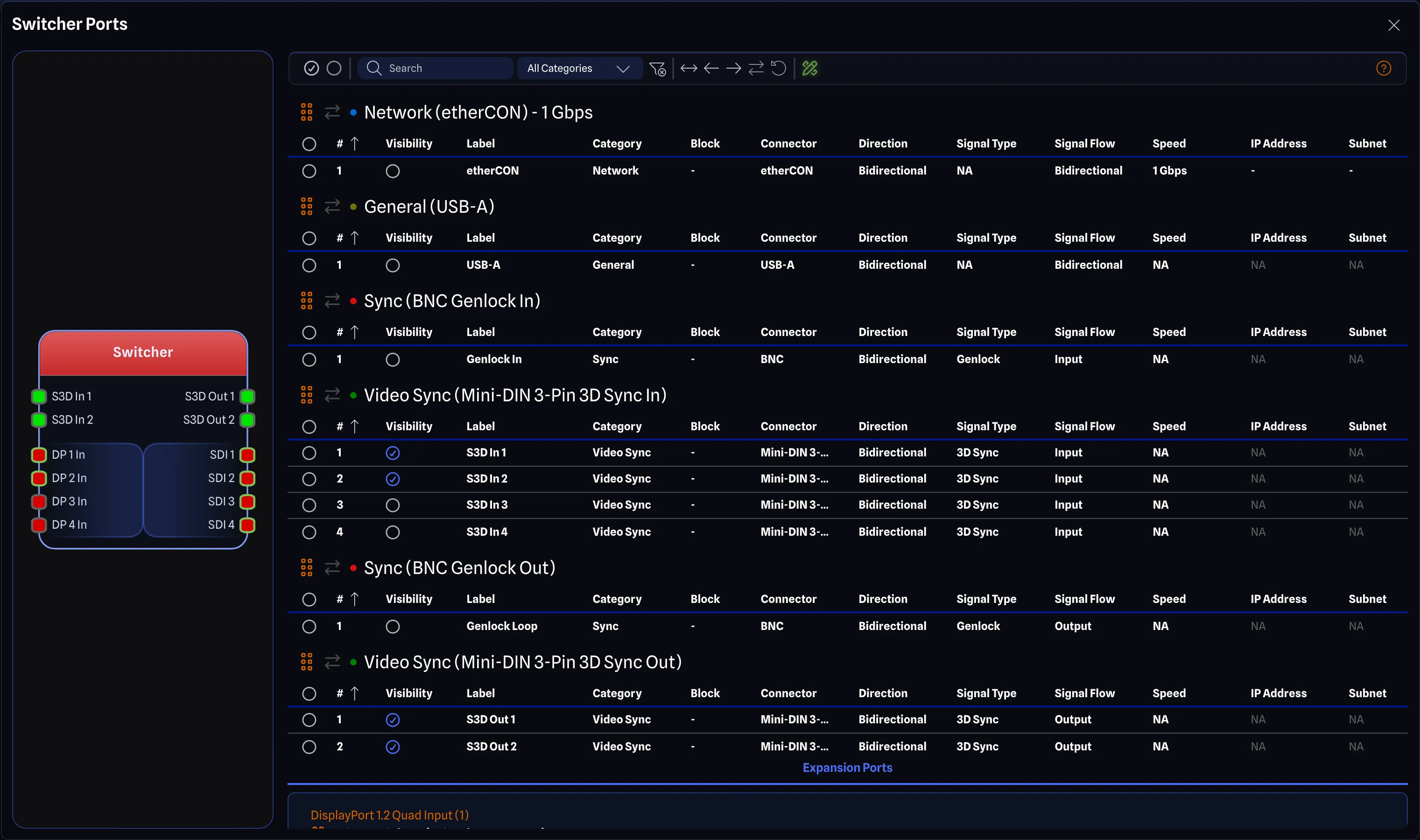
You can toggle Full Edit Mode by clicking on the Enable Full Edit Mode button in the toolbar. This will allow you to edit all the port options for the selected gear item. When this mode is disabled, you will only see options that have configuration options, as defined in the library item, using Multi-Mode. You can learn more about Multi-Mode at Library Port Options and you can learn more about the various port options at Gear Port Options.
When editing the Category, Connector or Signal Type of a port, a categorized selector menu appears with search and keyboard navigation. See Using the Categorized Selector for details on how to use this menu.
If you change a port option on a connected port and the new value is not compatible with the port at the other end, a Connection will be removed dialog explains why and asks you to confirm. Continuing removes the connection, and cancelling leaves the port as it was. A change that keeps both ports compatible leaves the connection in place.
Full Edit Mode will persist across all projects on the same device, so once you enable it in one project, it will be available in all other projects until you disable it.